
Serving Customers in Residential, Commercial, and Industrial Markets Worldwide
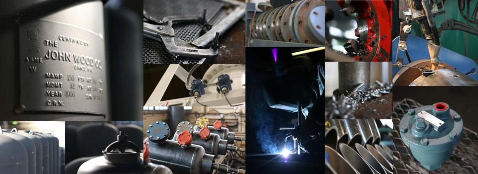
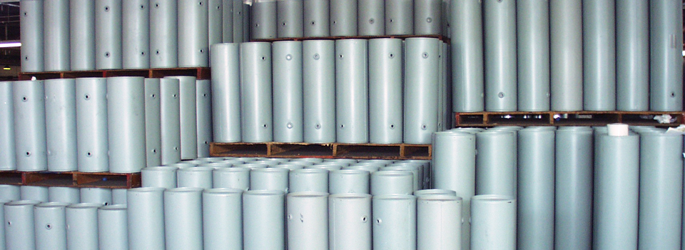
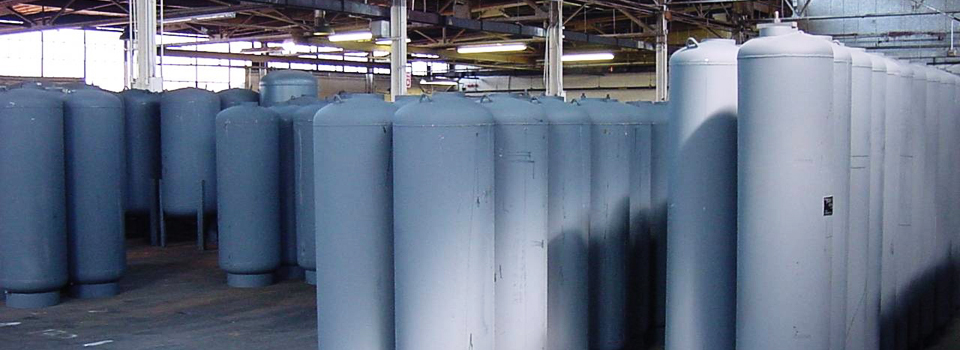
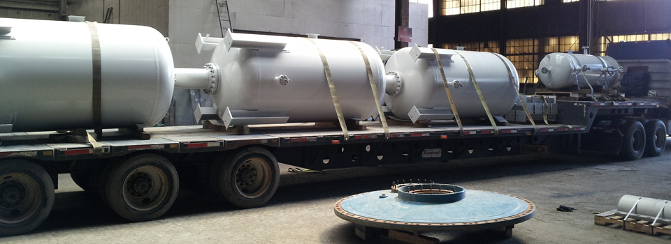
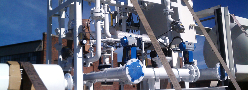
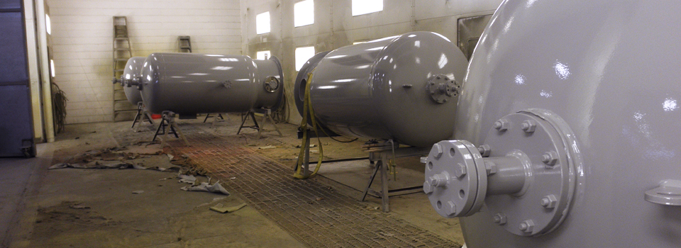
The John Wood Company, LLC, serves customers in residential, commercial, and industrial markets worldwide. With a broad product portfolio that includes water storage tanks, ASME pressure vessels and custom fluid handling systems, we strive to meet the needs of our customers by building strong relationships and by providing the highest customer delivered value.
 Our products are proudly fabricated and made in America!
Sales: 610-666-1220 or 920-939-2819
Certifications
- ASME Section VIII, Division 1
- Pressure Equipment Directive (PED) 97/23/EC
- Canadian Registration
- American Bureau of Shipping (ABS)
- US Coast Guard (USCG)
- American Water Works Association (AWWA)
Highlights
- Large inventory of standard products available for immediate shipment
- Inventory stocking programs for OEMs
- ASME Plus quality assurance
- Engineering and design support utilizing the latest version of Solidworks 3D CAD modeling